Leak Sealing – Case Studies
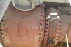
B. LEAK SEALING OF 48” NB ANSI 600 GAS LINE FLANGE
a. A Mating Flange on 48” NB ANSI 600 Gas Pipeline developed a leak through the Gasket.
b. The studs were re-torqued after pressure reduction.
c. The leak could not be reduced due to the Retightening procedure.
d. It was decided that the only feasible method to seal the leak was with a FLANGE LEAK CLAMP.
e. Pipeline Location : Middle East Desert
f. Ambient Temperature : 46.5°C
g. Design Temperature : 65°C
h. Operating Pressure : 97 Bar
i. Medium Transported : Natural Gas
j. Fabrication Schedule
| Day 1 | • Receipt of Drawings from Location • Submission of Clamp Drawing • Submission of installation Procedure |
Day 2 | • Approval of clamp Drawing. • Approval of Procedure • Requisition and Receipt of material • Fabrication of test Rig |
| Day 3 | • Raw Material identification • Shell Plate Cutting & Bending • Stiffener Cutting & Machining • Fit up for welding • Welding shell to stiffener |
Day 4 | • Post Weld Heat Treatment • Machining of seal grooves • Moulding of seals • Arrangement for packing material |
| Day 5 | • NDT of Welds • Hydro test of clamp • Blasting and Paint Primer Application |
Day 6 | • Clamp weight: 1600 kgs • Packing and dispatch by dedicated Flight • Receipt of clamp at Destination • Country & Custom clearance |
| Day 7 | • Installation of clamp • Injection of sealant • Line operating at desired Pressure |
Day 8-10 | Issue of P.O. + Confirmation of Commercial Terms |
k. Action initiated after leak repair
i. All Flange Connections were listed and documented.
ii. Flange Size and Rating with Unique identification No. provided for all Joints.
iii. The Misalignment between Diameters of mating flanges noted.
iv. Flange Leak Repair Clamps are procured and stocked as per total quantity.
v. Equipment for clamp installation and sealant are now stored at the same location with Flange Leak Repair Clamps.
vi. Projects, Design & QC Departments were directed to submit the following documents for New Projects :
Unique Flange Identification No.
Torque Applied during tightening.
Misalignment between mating Flange diameter.
Ensure sufficient gap is maintained adjacent to Flange Joints


